The steps are as follows :
1 . Preparing and Observing Motherboard
1 . Preparing and Observing Motherboard
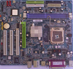
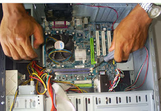
- Prepare the motherboard and note the position of the components available to it for more details
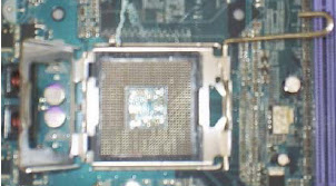
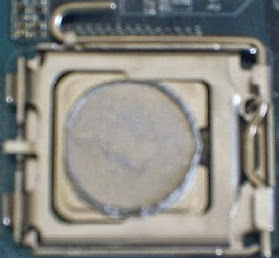
- After that open the lock socket processor .
2 . Take Processor .
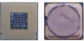
- Note that the processor has a sign on one of its corners , in this case usually marked with indentations , holes or darts
- Skewer these markers with markings on the processor socket .
- If you do the above correctly , then the processor would be inserted into the socket properly
- The back key socket , by pressing the lever down and hook the existing lock
3 . Installing the Heatsink and Cooling Fan .
- Heatsink and fan are already assembled into one , so we just stay put and to set it up is easy
- Before installing , note the position of the power cable to the fan power connector location . Find the shortest distance so that it does not touch the power cord with a fan
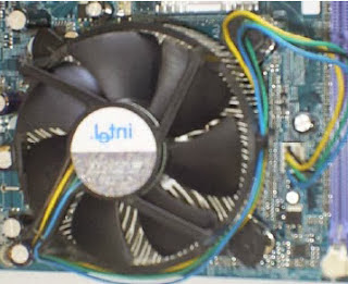
- In the example of the Pentium 4 heatsink cooling times this form is round and there are 4 on 4 point locking around the cooler .
- Install the heatsink is a way to put it right on top of the processor and cooling sesuikan holder on the existing motherboard .
- 4 key points on the cooling by means press and turn clockwise using a screwdriver plus ( + ) .
4 . Installing the Memory
- To install memory , then open the lock on the second memory slot on the motherboard side
- Perhatihkan that each memory chip has a crack on the bottom side . At this time we are using the practice of double data rate random access memory ( DDRAM ) . There are other types of RAM , but currently hard to find in the market in new condition called syncronous dynamic random access memory ( SDRAM ) .
- Match this gap with a memory slot . If you were forced to install memory in the wrong direction , it can damage the memory or the motherboard.
- Press the memory chips on both sides so you hear a " click" , and the latch will close by itself
5 . Casing prepare .
- Prepare the chassis to be used .
- Place on a table or other places that are considered safe .
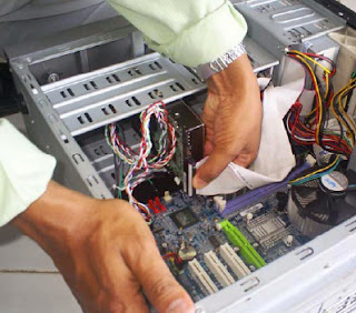
- Remove the existing screws on the back , and then open the side panel carefully , as shown below ini.d. Press the memory chips on both sides so you hear a " click" , and the latch will close by itself
- Match the position of the motherboard with the existing holder in the casing .
- Make sure the legs are going to support you in the motherboard that requires a strong pressure , such as the processor socket or slot memory . Do not forget any existing motherboard mounting bolt holes must be given screw / bolt , so a strong position ( not wobbly ) .
6 . Installing the Motherboard
- Prepare screws and screwdrivers are used , then attach your motherboard correctly on the stand are available
- Be strong ( turn clockwise ) all the screws that are used for the motherboard is good and right .
7 . Setting up a hard drive
- Take your hard drive , and note the jumper . Jumper will be an option on the Master , Slave or Cable Select . This information can be found on the surface of the disk .
- Put the jumper in accordance with the desired position . If necessary, prepare a pair of tweezers to remove and install a jumper on the hard drive .
8 . Replacing the hard drive to the chassis .
- Some manggunakan casing bracket system that can be removed to facilitate the installation of the hard drive and cd / dvd drive
- Choose the appropriate screws , do not get too big or too long , then attach the mounting screws on the hard drive properly .
9 . Connecting the hard drive to the motherboard .
- Note that there are two types of IDE data cable , which is 40 - wire and 34 - wire . 40 - wire cable is used for the hard drive and cd / dvd drive
- This data cabling should not be reversed . On one side there is usually a cable with red color indicating pin number 1 .
- This position is also marked on the hard drive . Normally the position of pin 1 on the disk ( red wire ) is right next to the power connector ( in red ) .
10 . Installing the Floppy Disk Drive ( FDD ) .
- Installing the Floppy drive , about the same as installing hard drive , except for a few models that separate the casing and the floppy disk .
- Some types of casing , probably need to open the front panel before installing the floppy disk drive .
11 . Setting up the CD / DVD Drive .
- Like the hard drive , CD / DVD drives also use the jumper to the position of Master and Slave . Set jumper proficiency level in the desired position .
- If only there is a hard drive , the jumpers are in the position of Master .
- If there are 2 hard drives on one computer and both are enabled , then the first hard disk drive used as masters and only have to set to Slave .
12 . Installing a CD / DVD drive .
- To install the CD / DVD drive usually we need to disconnect chassis front panel first, or depending on the type and model of the used casing .
- Opening the drive cover on the front panel .
- Install a CD / DVD drive correctly , then close the front panel ( if using the front panel ) .
13 . Connect CD / DVD drive to the motherboard
- IDE data cable installation from CD / DVD to the motherboard together with the installation disk .
- Plug connector CD / DVD , and the other end to the motherboard , the connector labeled CD
- Do not forget to tidy up the cables that were disconnected and " chaotic " . Set the track and cable lines neatly , if necessary tie to make it more presentable and pleasing to the eye .
14 . Connecting Cable Connector on Motherboard
- Now we need to connect the cables from the motherboard to the chassis
- This cable consists of power switches , drive indicator , power indicator , reset button and speaker, as shown in the picture below .
- For chassis that provides front panel , such as universal serial bus ( USB ) , then the wires should be connected to the motherboard in order to function normally .
15 . Connecting the Power Cord
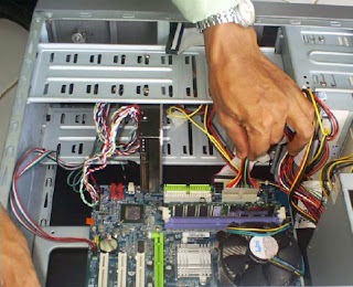
- After all is installed , then the next step is to connect the power cord from the power supply to the motherboard , hard drive , FDD and CDROM
- For the Pentium 4 motherboard , usually there are at least 2 dayayang connector should be installed , as shown below .
- Then connect the power cables also to the hard drive , floppy , and CD / DVD . If you use a chassis cooling fan , then connect it to the power supply or to the motherboard , according to the connector held .
16 . Prepare Components Outside
- If the internal components are wrong , it now turns komponenkomponen the outside , such as the monitor , keyboard , mouse and speakers

- For these components , we just connect the wires to the terminals that have been determined , such as keyboard , mouse , speakers and others.
- Do not forget to power cables , both for the chassis and the monitor .
17 . Checking the Power Supply
- Check carefully for the power supply is used . Normal voltage is 220-230 volts . If the switch is provided , then move the switch to the appropriate voltage source
- Some are equipped with a power supply voltage of the transfer ( switch ) between 110 or 220 volts .
18 . PC Brother It's Ready
- Now your PC is completely ready , and could in his power supplynya . Do not forget before mengONkan Power Supply is to always " pray " first.
- If you do not want to check once again the power wiring ( source voltage ) that is used to supply the computer device
19. Good Luck..




Tidak ada komentar:
Posting Komentar